Justin W.H. Yuen
Reverse Engineering Project: Making a Solid Model of a Hobby Propeller
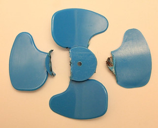
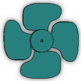
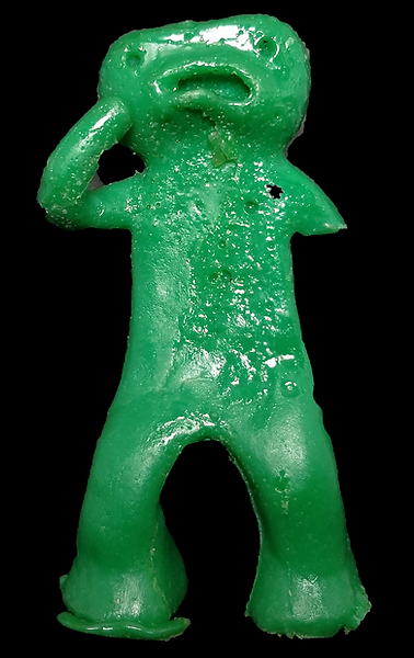
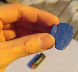
Hobby Propeller (left) and Solid Model (right)
Modeling this object with multiple lofts would be difficult and painful considering its longest dimensions were no more than 4 cm. Instead, I took a creative approach by using the contour of the blades and tracing the top view of the propeller. To measure easier, I cut 2 of the blades off.

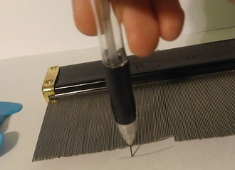
Using a contour gauge (left) and tracing the contour with a pencil.

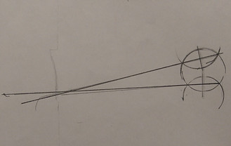


Scanned tracing of the contour gauge (top left), radius of curvature determined geometrically (top right), sweep profile from inserted image feature on SolidWorks (bottom left), and resulting sweep (bottom right).


The most difficult part was getting a decently leveled picture of the top view. Using a leveled printer scanner would typically do the trick, but I couldn't get a clear picture. So I came up with an idea to use spray paint. The idea came from spray paintings I used to make using stencils.

Red spray paint (top left), taped propeller blade (top right), propeller painted over (bottom left), and stenciled mark beneath propeller (bottom right)


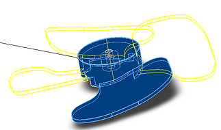
Stenciled spray paint (top left), tracing of the painting (top right), extrude cut preview (bottom left), and final result of the propeller blade (bottom right)


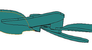
Extrusion of hub (top left), extrude cut under the blade (top right), circular pattern (bottom left), final model (bottom right)

Other than avoiding multiple lofts to model the blade, I now have an easier way to redesign the contour and shape of the blade.