Justin W.H. Yuen
Differential Gear System
A fun project to learn and practice manufacturing and fabrication machines and tools including CNC's, lathes, and drill presses.
Manufacturing Course, Spring 2018
Goal
Design and manufacture a model differential gear system using SolidWorks's HSM program.
Results
A portable and functional model of a differential gear system.

When a car turns, wheels on one side of the car will rotate at a different speed from the other side. A differential gear system is used to allow one side of the car's wheels to keep spinning if the other slows down or stops completely. As you can see above, our working differential model demonstrates that!
Approach
Design a gear system and manufacture them with a CNC machine using 3D HSM features
Machines and Tools
CNC milling, CNC lathe, drill press, power drill
Purchased materials
HDPE sheets, HDPE rod, open ball bearings, steel shafts
Making the Gears

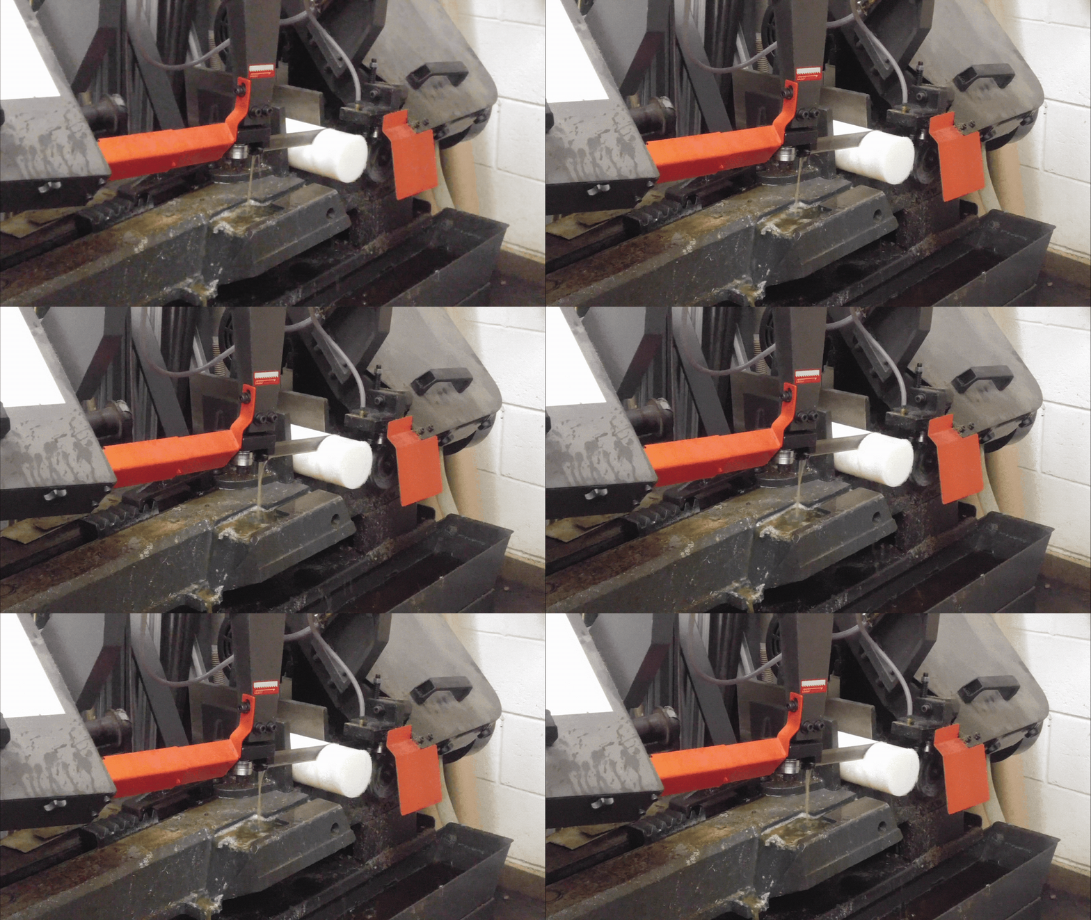
Before using the CNC machine, we divided the stock HDPE rod into sections for our small gears using a horizontal band saw.


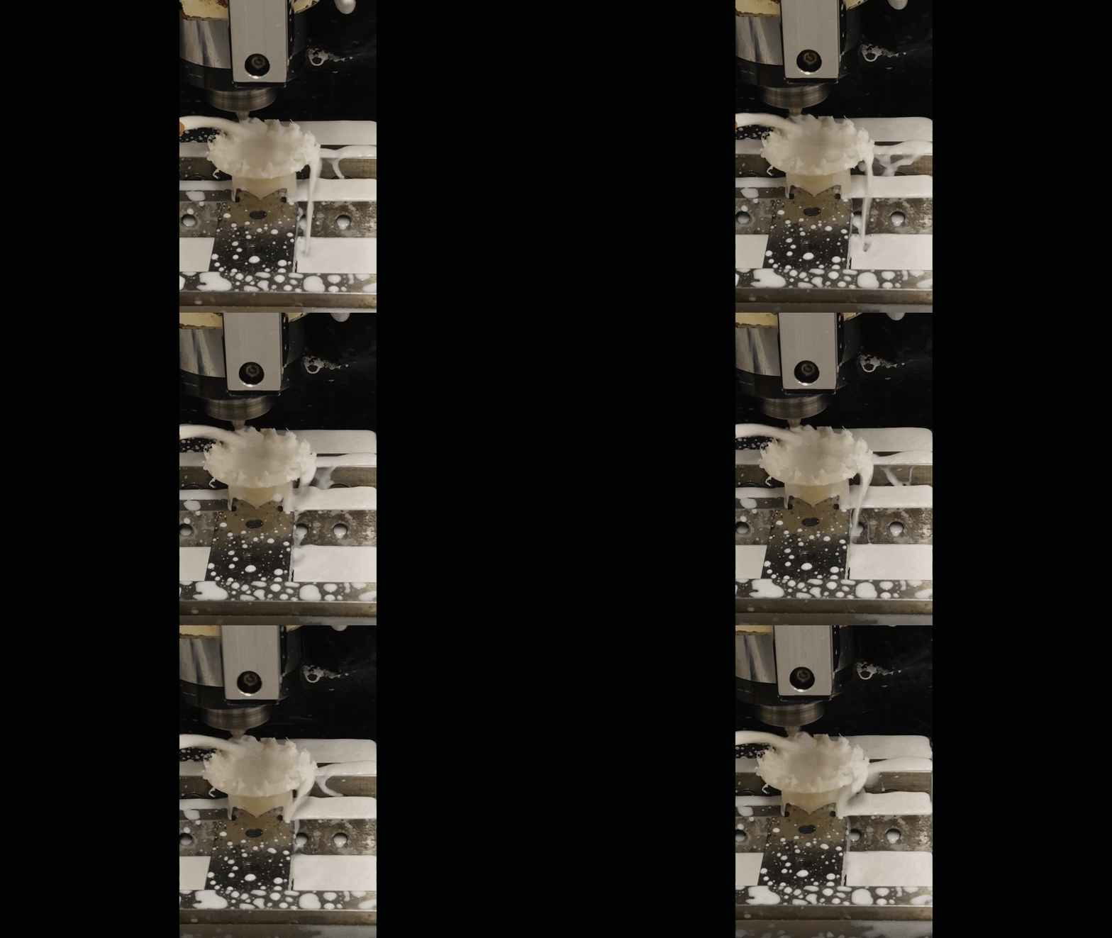
On the left is a simulation made with SolidWork's HSM features, and on the right is the actual CNC process. Below is a comparison of the stock and completed gear.

Housing and Final Touches

Scrap wood was used to make the housing and stand for the differential. Steel rods were used as the shafts for the gears and the bearings were hidden within the wooden planks.

Wheels were drawn on circular planks for visual aid in demonstrations.
Results

Murphy's law truly tested us this semester. Budget issues forced us to reorder our materials from a different distributor, the materials came late, and there was only time in the course to learn how to CNC 2D objects. Considering we had to adapt to these unexpected problems, and having to teach ourselves how to CNC in 3D, we make up for the lack of aesthetics with our wits to provide a timely delivery of a functional model. Our project remains in the manufacturing lab as a display of our hard work.